The 4th Dimension
This page is a WIP and is currently accessible by participating members onlyIndex:
(A) IntroductionAbstract
Aim
Objectives
(B) Material Archive
(C) Nomenclature
(D) Interlocks
Introduction
Description
Materials
Helpful Software
Understanding
Types / Position of indents
Voids and with indents
Diagramatic Examples
Reference Study
(E) Stacking
Introduction
Description
Materials
Helpful Software
Understanding
Cube
Tetrahedron
Sphere
Organic Sculpted Form
Staggered Stacking
Reference Study
(F) Folding
Introduction
Description
Materials
Helpful Software
Understanding
Symbols Nomenclature and types of folds
Crease and crease patterns
Deployable Structures
Surface Development for Simple and complex surfaces
Reference Study
(G) Bending
Introduction
Description
Materials
Helpful Software
Understanding
Patterns to bend sheet materials
Reference Study
(A) Introduction
Abstract:
Designers often use easily available sheet materials for quick construction and prototyping purposes. But a lot of these methods can also be used to create sustainable products by inspecting material usage, availabilty and crafting simple methods of making. To do this, one has to first understand easily available materials and their attributes.
Every readily available sheet material has its own physical propeties which might pose as limitations. To create an understanding that is free of this, we study characteristics of a 2D Planar geometry & observe the process it can go through to become a 3D form.
Thus, to have an open understanding of possibilities, we have explored the processes of interlocking, stacking, bending and folding in our study.
The forth dimension is an experimental case study that is an ode to planar geometries attempting to form 3 dimensional sculptural creations. This study consists of forms as by-products.
It will be expressed into an open source of DIY parametric furniture kits, made through the participation and collaboration of multiple desingers.
Aim:
To understand how to create 3D forms from 2D planar geometries.
Objectives:
• Develop a material archive of easily available sheet materials. Compare their attributes, and map their limitations.
• Understand Interlocking mechanisms for tool-less construction, without glue or screws.
• Understand methods of stacking sheet materials to develop corner joineries and amorphous forms.
• Understand different methods of modular folding and complex surface development.
• Understand parametric patterns that allow sheet materials to bend in multiple axes.
• Look into extension, expansion and other attributes that would be restricted only to thick sheet materials.
• Express our understanding into an open source of parametric furniture pieces.
It will use local readily available materials and resources with minimum wastage and a DIY method for construction.
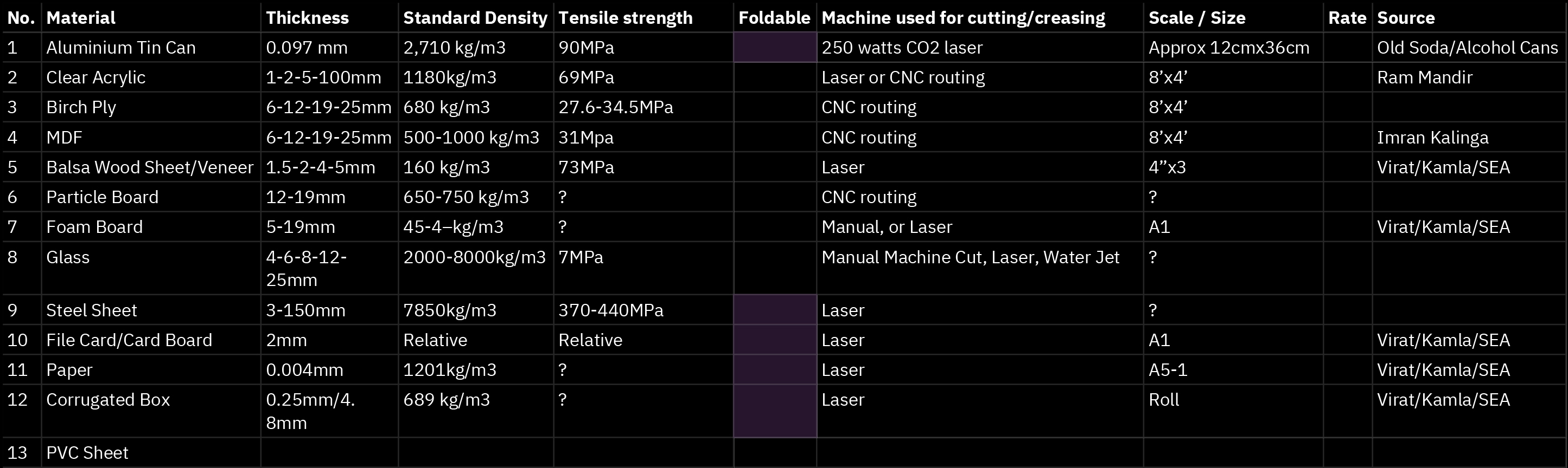
(B) Material Archive
Every material has its own restrictions based on its physical properties, we have created a comparative local list of materials that fit into the category of two dimensional planar surfaces.
(C) Nomenclature
 Two dimensional planar surfaces (2D plane)
Surfaces where the thickness is extremely less compared to its length and width. Also referred to as thin surfaces or sheets.
They do not exist in the physical world.
Since every physical material has some thickness to it.
 Indent/Incision/Notch
Is a cutout on the surface, where the,
thickness of the surface is usually equal to the width of the cutout. If the width is greater than the thickness it is considered to be a void.
 Void
VoidA void is also a cutout on a surface whose form is not restricted. It can be of any size and shape within the area of the surface.
 Interlock
When 2 or more surfaces fit into each other either through indents, sliding or stacking
 Stack
StackIs piling up/ overlapping of multiple surfaces on top of each other in a particular arrangement.
 Fold
FoldBend something along a defined crease line to morph its appearance and/or strength
 Bend
BendWhen a surface with low tensile strength is forced to curve along a single or multiple axis
Misc. Definitions:
• A slit made perpendicular to the thickness of a material is called a kerf. This could either be made by a saw, or a CNC mill/laser.
• Units used to measure thickness: mm
• Instrument used to measure thickness:
Vernier calliper or Screw gauge
• A slit made perpendicular to the thickness of a material is called a kerf. This could either be made by a saw, or a CNC mill/laser.
• Units used to measure thickness: mm
• Instrument used to measure thickness:
Vernier calliper or Screw gauge
(D) Interlocks
Introduction
Description:
Interlocking mechanisms are the simplest and the most efficient way to join 2D planar geometries. They assist a tool-less, no glue, no screw construction process.
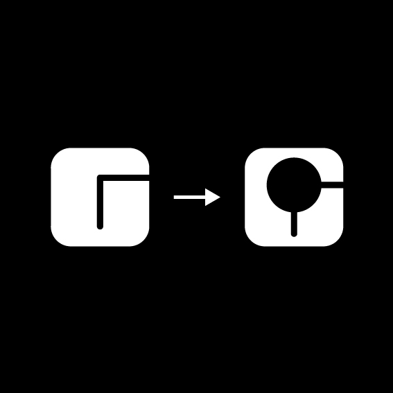
The crux of interlocking 2D planar geometries, lies in the position and shape of the indent. An indent can either be positioned on the edge or on the surface itself. After identifying different forms of indents, we built an analog algorithm that explores permutations and combinations of different kinds of interlocks and their applications.
With the same understanding, we have also explored the combination of interlocks with voids through a few examples.
Materials:
• Ply wood Sheet
• Acrylic Sheet
• MDF Sheet
• Particle Board Sheet
• Balsa Wood Sheet
• Foam Board
• Corrugated Card Sheet
• Card Board
Helpful Software:
• Deep Nest (Nesting Software)
• Autodesk Fusion 360 (Parametric Software)
• Sketch Up or Rhino (Conceptual Modeling)
• Autodesk Autocad (CAD)
Understanding
Types of Indents
Following are categoriesed cases based on the position of the indent on the two dimensional plane.
They are kept in a simple rounded rectancgle form for easy understanding.
Indents positioned on the edge of the two dimensional plane (A-E)
Indents positioned on the surface of the two dimensional plane (F-J)
Miscellaneous Cases (K-M)
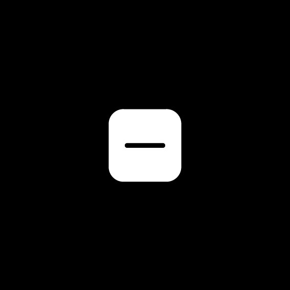
 A
A
Single Orthogonal Indent on Edge of 2D plane
 B
BL-Shaped Indent on Edge of 2D plane
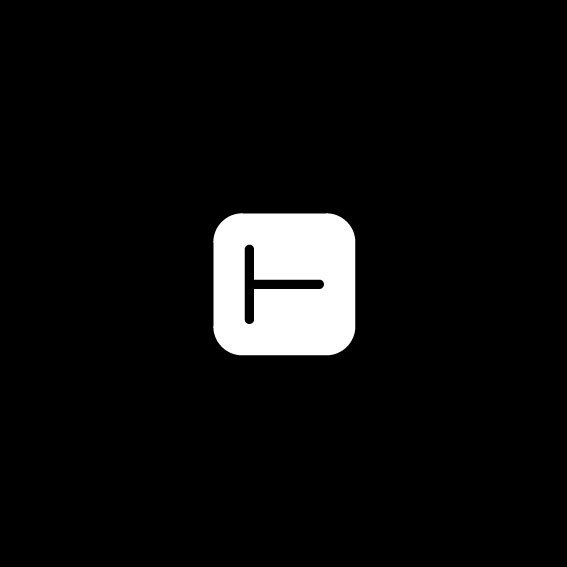
 C
CT-Shaped Indent on Edge of 2D plane
 D
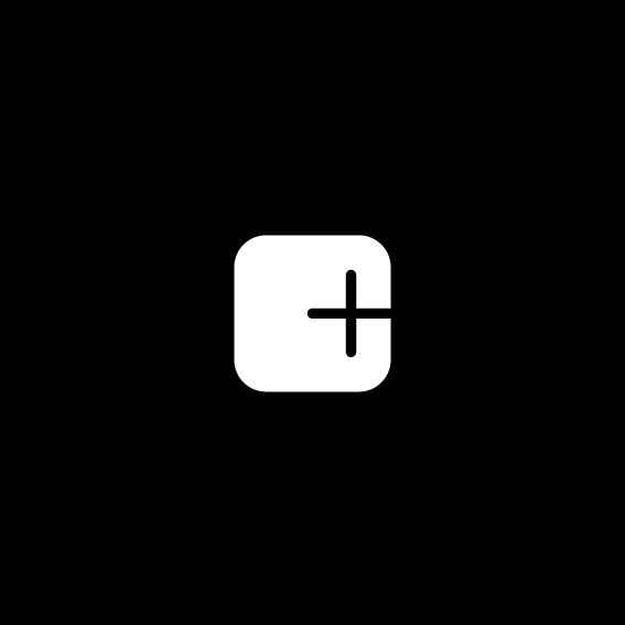
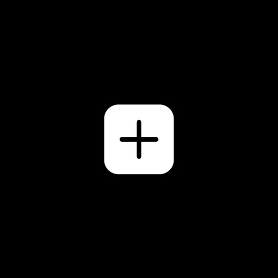
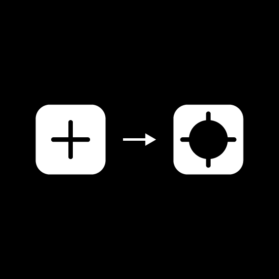
D+-Shaped Indent on Edge of 2D plane
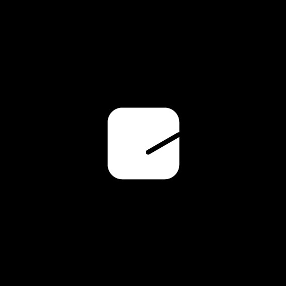 E
ESingle Oblique Indent on Edge of 2D plane
 F
FSingle Orthogonal Indent on Surface of 2D plane
 G
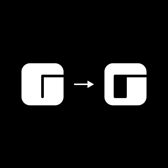
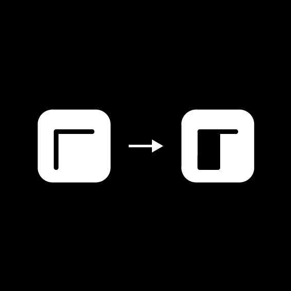
GL-Shaped Indent on Surface of 2D plane
 H
HT-Shaped Indent on Surface of 2D plane
 I
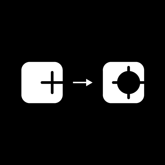
I+-Shaped Indent on Surface of 2D plane
 J
JSingle Oblique Indent on Surface of 2D plane
 K
KMultiple Edge indents on 2S plane
 L
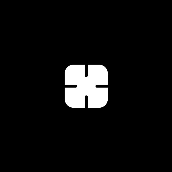
LMultiple Intersecting Surface Indents on 2S plane
 M
MCircular Void on Surface of 2D plane
Voids + Indents
Combining indents with voids often helps in the following ways
• Allows interlocking multiple parts through the same void.
• It also guides the turning of secondary parts.
• Attaching a void to an indent helps in interlocking parts bigger in size. In this case the part size will be related to the size of the void and not the indent.
• Circular voids are preferable for 360 degree turning and locking of another material.
Here are a few 2D planes that feature the combination of voids and indents.
 V1
V1A rectangular void added to part B
 V2
V2A rectangular void added to part G
 V3
V3A circular void added to part B
 V4
V4A circular void added to part I
 V5
V5A circular void added to part D
 V6
V6An indent attached to part M
 V7
V7Indents attached to the edges of triangular voids
The Matrix
A representational graphical matrix that reflects an analog alorithmic approach to interlocking.
The exercise attempt to comibine the 10 different types of indents, with each other in a multitude of permutations and combinations.
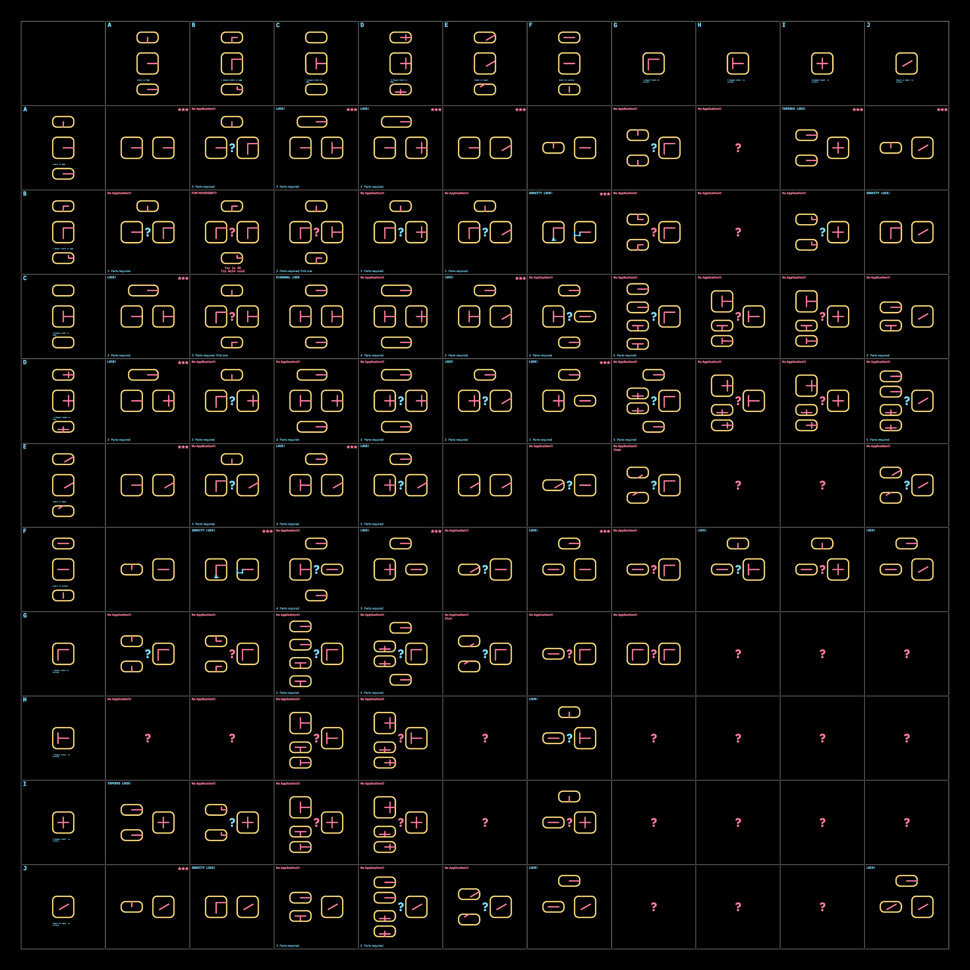
This symmetrical diagram definately makes the process look more complicated than it is.
Observations:
• L-shaped indents on edge (B) work the best when one indent from the L is made wider, for a gravity lock mechanism.Could be used as an example for combination with voids.
• +-shaped(C) and T-shaped(D) shaped indent on edge behave almost the same, and help interlocking in 3 axes.
• Angled indents (J) will behave the same as orthogonal incisions.
• When indent is on the surface of a 2D plane, the other parts need to be as wide as the length of the Indent, in order to pass through.
• No uses recognized for L-shaped (G) and T-shaped (H) indents on the surface of a 2D plane.
• Turning and locking is only possible with a void attached to an indent on a 2D plane.
Here are a few useful curated combinations based from the matrix
Simple two piece interlocks:

AA
Two identical surfaces with orthogonal notches interlocking into each other
 EA
EAAN oblique notch interlocking to a othtogonal notch
 EE
EEInterlocking two surfaces with obliques notches

FA
The width of the interlocking surface needs to be equal to the length of the indent on the surface
Three piece interlocks, are used as locking mechanisms in three axis. Their main application is used in joineries where the use of glue or screws is restricted.
 EC+A
EC+AParts interlocking in three axis creates a locking mechanism
 FC+A
FC+AParts interlocking in three axis creates a locking mechanism
FD+A
Parts interlocking in three axis creates a locking mechanism
ED+A
Parts interlocking in three axis creates a locking mechanism
JC+A
 CA+A
CA+A DA+A
DA+A
FF+A
 IA+A
IA+AWe have also curated a few fun form compositions, which might not have any particular function. But are just a by-product of the exercise.
 BA+A
BA+A CC
CCUseful for angular parts to pass through
DC+A
 G+CA+CA
 DD+A
DD+A EB+A
EB+A
FE
DB+A
 JE
JE GA
GA G+DA+DA
 G+EE
G+EEWhen voids are combined with indents, they assist interlocking of bigger sized parts as well as turning.


Reference Study
 Julien Nolin Ws22
This meticulously crafted furniture piece not only takes into account interlocking mechanisms, but also the material usage.
 Nobel Truong
(E) Stacking
Introduction
Description:
Multiple parts of sheets materials can be stacked up and stuck together to form 3D objects. The various parts involved can be simulated digitally as well as crafted manually. A basic analogy would be to stack up slices of bread to make a loaf. Just imagine this loaf to be a 3 dimensional form.
Stacking of sheet materials in a staggered fashion can also be used to design orthogonal corner joineries as well as simple channel guides to assist sliding.
This method often requires a bonding material like glue to stick all the pieces together. The joining can also be done through interlocking mechanisms.
Here we have investigated available digital tools that assist the process of converting amourphous forms into stackable parts. Along with a few examples for corner joineries and their applications.
This will help you to get a basic understanding of what the possibilities with this process could be.
Materials:
• Ply wood Sheet
• Acrylic Sheet
• MDF Sheet
• Particle Board Sheet
• Balsa Wood Sheet
• Foam Board
• Corrugated Card Sheet
• Card Board
Helpful Software:
• Slicer for fusion 360 (Slicing Software)
• Deep Nest (Nesting Software)
• Autodesk Fusion 360 or Grasshopper for Rhino (Parametric Modelling)
• Blender or Cinema4D (Digital Sculpting)
• Sketch Up or Rhino (Conceptual Modelling)
• Autodesk Autocad
Understanding
Cube
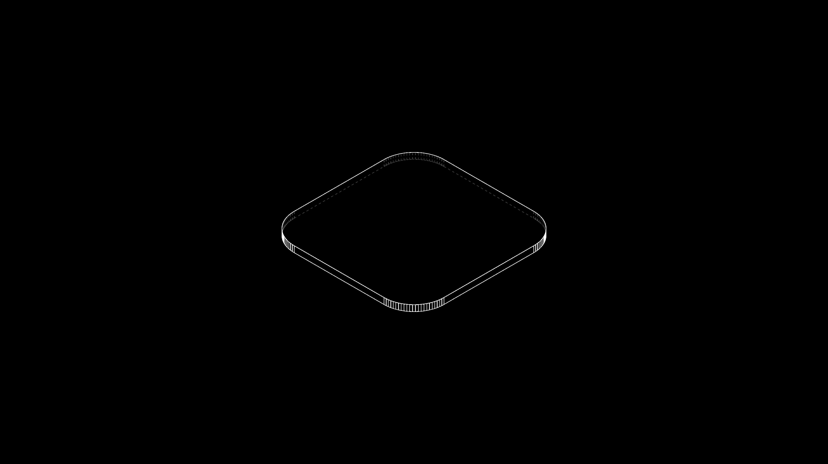
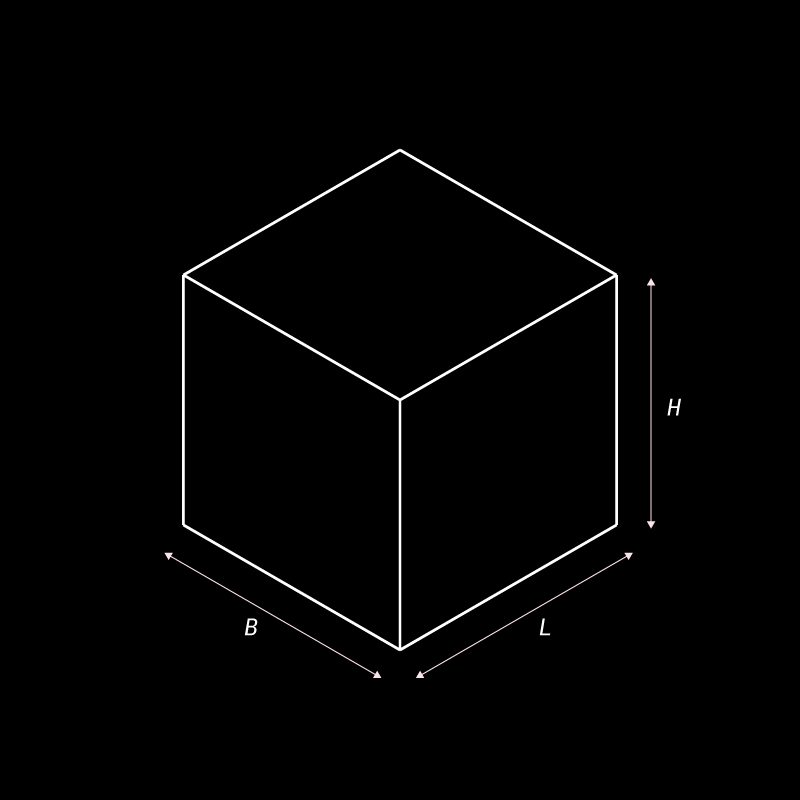
Understanding the process of forming a cube out of stacked surfaces.
Dimensions:
![]()
• Surface Spacing or thickness (T)
• Length of cube (L)
• Breath of cube (B)
• Height of cube (H) Here, that direction of stacking is considered to be along the height. This can be altered based on the requirement
• Surface Spacing or thickness (T)
• Length of cube (L)
• Breath of cube (B)
• Height of cube (H) Here, that direction of stacking is considered to be along the height. This can be altered based on the requirement
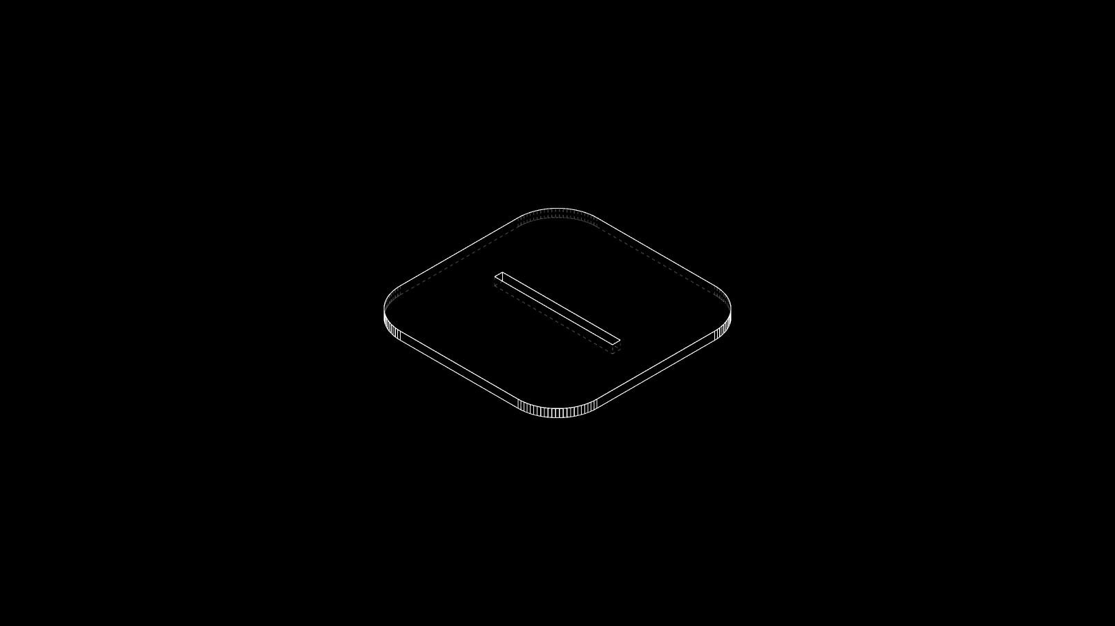
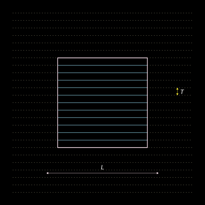
Profile construction:
![]()
In this case the profile would be the the length and the breath.
Since the stacking is done in the direction of the height.
In this case the profile would be the the length and the breath.
Since the stacking is done in the direction of the height.
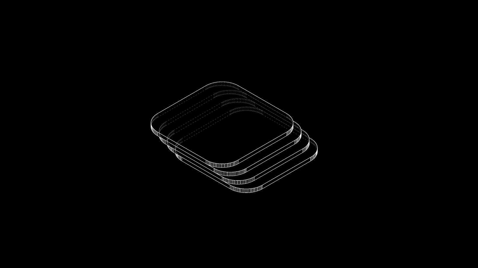
Surface Profiles:
![]()
Number of parts(N): H/T
Here the number of parts is determined by the spacing and the distance to be stacked
Number of parts(N): H/T
Here the number of parts is determined by the spacing and the distance to be stacked
Tetrahedron
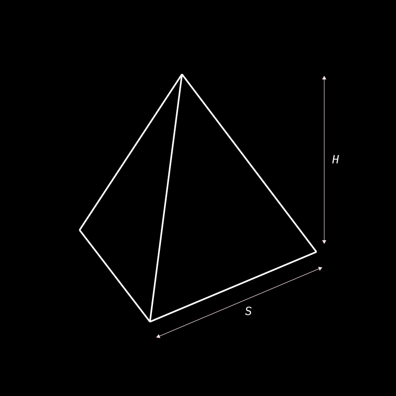
Understanding the process of forming a tetrahedron out of stacked surfaces.
Dimensions:
![]()
Surface Spacing or thickness: T
Side of Tertagedron (S)
Height of Tertagedron (H)
Here, that direction of stacking is considered to be along the height. This can be altered based on the requirement
Surface Spacing or thickness: T
Side of Tertagedron (S)
Height of Tertagedron (H)
Here, that direction of stacking is considered to be along the height. This can be altered based on the requirement
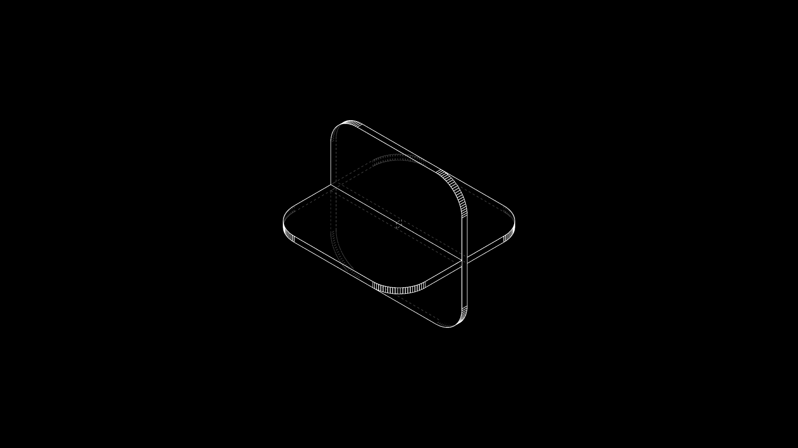
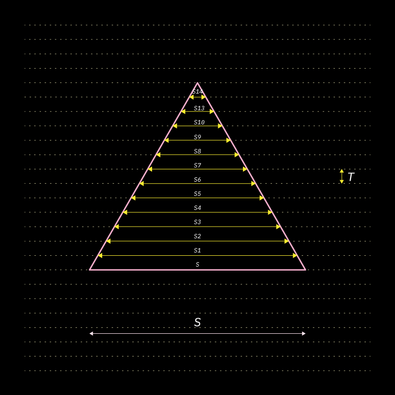
Profile construction:
![]()
The profile sizes would variate.
This is because the side (S) of each trigular profile stacked would be determined by the surface spacing/thickness (T) intersecting the profile of the base triangle.
The profile sizes would variate.
This is because the side (S) of each trigular profile stacked would be determined by the surface spacing/thickness (T) intersecting the profile of the base triangle.
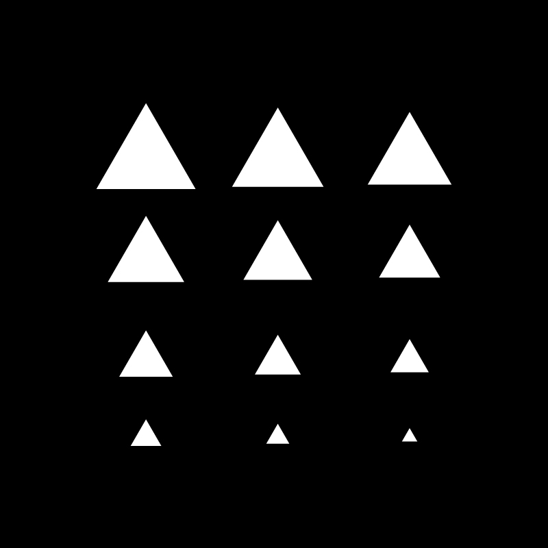
Surface Profiles:
![]()
Above you can view the sizes of the triangular profiels reducing.
Above you can view the sizes of the triangular profiels reducing.
Sphere
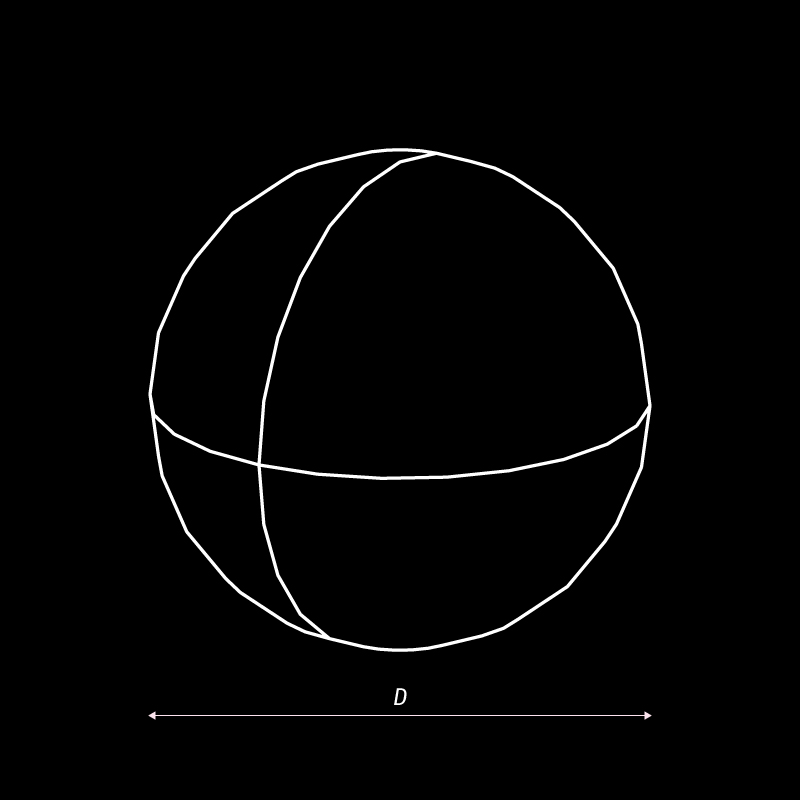
Understanding the process of forming a sphere out of stacked surfaces.
Dimensions:
![]()
Surface Spacing or thickness: T
Diameter (D)
Number of parts= D/T
Surface Spacing or thickness: T
Diameter (D)
Number of parts= D/T
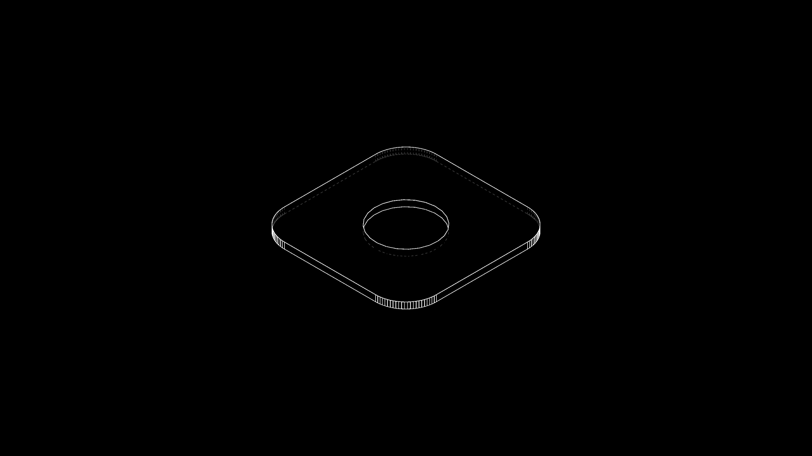
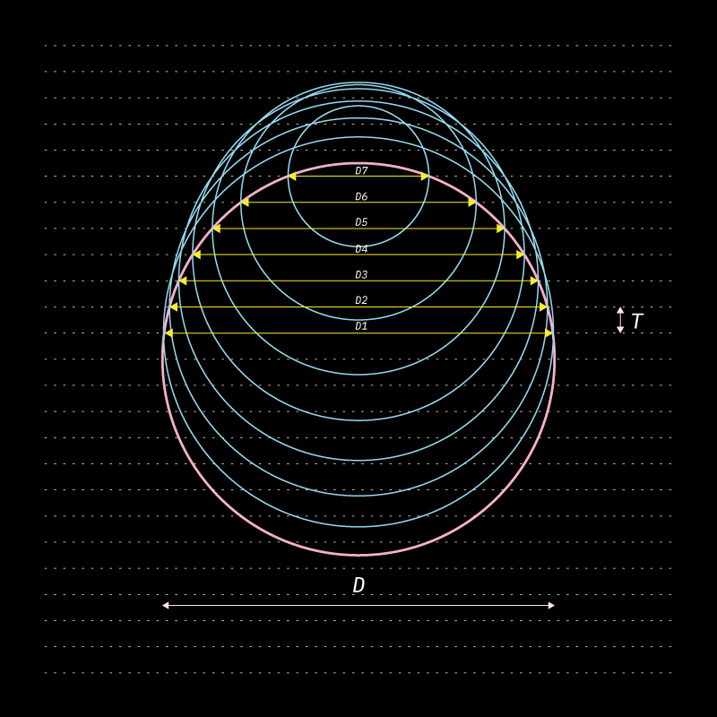
Profile construction:
![]()
The profiles would be circular in shape, and would reduce in diameter.
This diameter would be determined by the surface spacing/thickness (T) intersecting the profile of the base circle.
The profiles would be circular in shape, and would reduce in diameter.
This diameter would be determined by the surface spacing/thickness (T) intersecting the profile of the base circle.
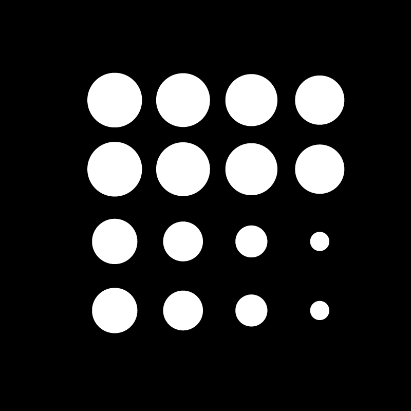
Surface Profiles:
![]()
Above you can view the reducing sizes of the circular profiles. Because the sphere is a symmetrical shape, the profiles beow and above the base circlur profile would be the same.
Above you can view the reducing sizes of the circular profiles. Because the sphere is a symmetrical shape, the profiles beow and above the base circlur profile would be the same.
Organic Sculpted Form
Understanding the process of slicing a sculpted form into stacked surfaces.
Organic Form:
![]() Digital Software for sculpting OBJ or STL files:
Digital Software for sculpting OBJ or STL files:
Autodesk Fusion 360
Rhino
Blender
Cinema 4D
If you have handsculpted the form or have a physical reference of the form you would want to model.
Click multiple images of your exisitng physical model and stictch them together.
This will help you generate a mock up of your physical model
 Digital Software for sculpting OBJ or STL files:
Autodesk Fusion 360
Rhino
Blender
Cinema 4D
If you have handsculpted the form or have a physical reference of the form you would want to model.
Click multiple images of your exisitng physical model and stictch them together.
This will help you generate a mock up of your physical model
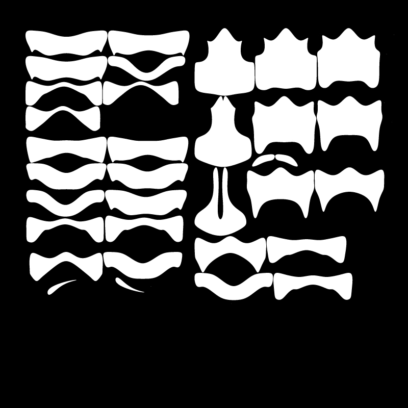
Surface Profiles:
![]()
Since all profiles would have a unique shape, digital aid simplifies the task.
To slice the digital model into multiple surfaces, we reccomend Slicer for Fusion 360.
Here are a few tutorials for reference:
Tutorial 1
Tutorial 2
This could also be generated by a grasshopper parametric script.
Since all profiles would have a unique shape, digital aid simplifies the task.
To slice the digital model into multiple surfaces, we reccomend Slicer for Fusion 360.
Here are a few tutorials for reference:
Tutorial 1
Tutorial 2
This could also be generated by a grasshopper parametric script.
Stacked form:
![]()
The parameters you need to keep in mind:
• Material
• Sheet size and thickness
• Axis of stacking
• Dimension of the model
• Method of attaching the surfaces together
(glue or screws)
The parameters you need to keep in mind:
• Material
• Sheet size and thickness
• Axis of stacking
• Dimension of the model
• Method of attaching the surfaces together
(glue or screws)
Staggered Stacking
Two dimensional surfaces that are thick can be stacked in a staggered form sectionally, to increase their joining applications.
These joineries can either be used to fix two staggered sufaces linearly or orthogonally to form edges and corners.
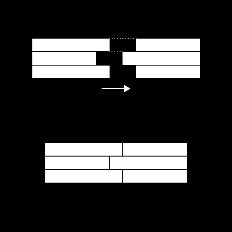
The below examples represent sectional views of thick two dimensional stacked surfaces:
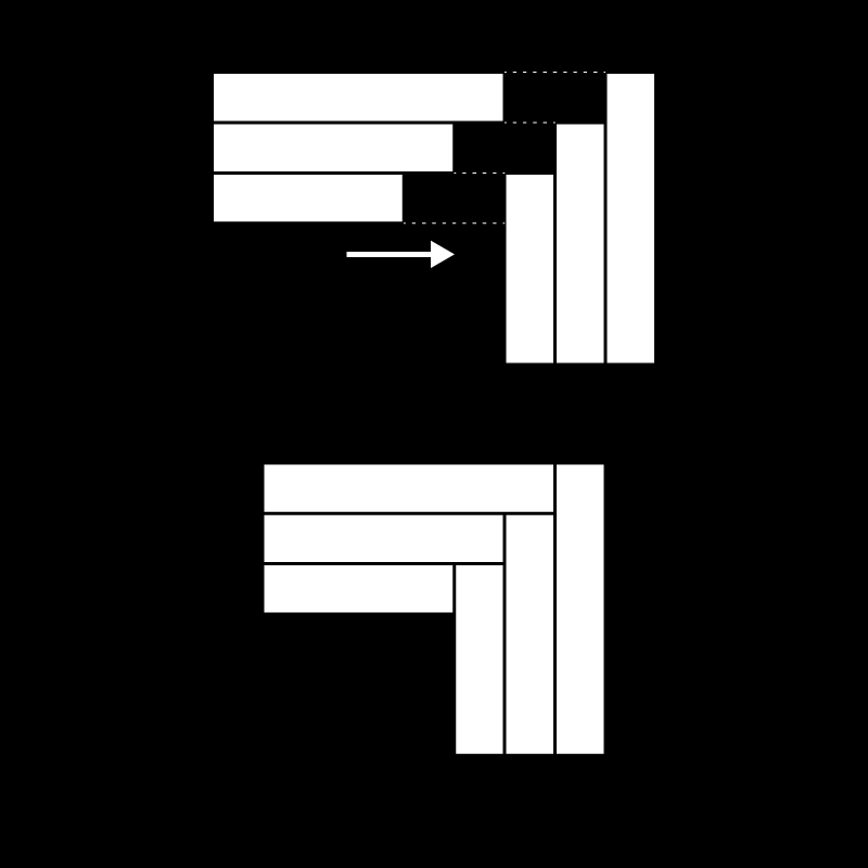
01. Corner Joint
Idnentical Stacked surfaces in a stepped stagger can be used to form orthoganal corner joineries
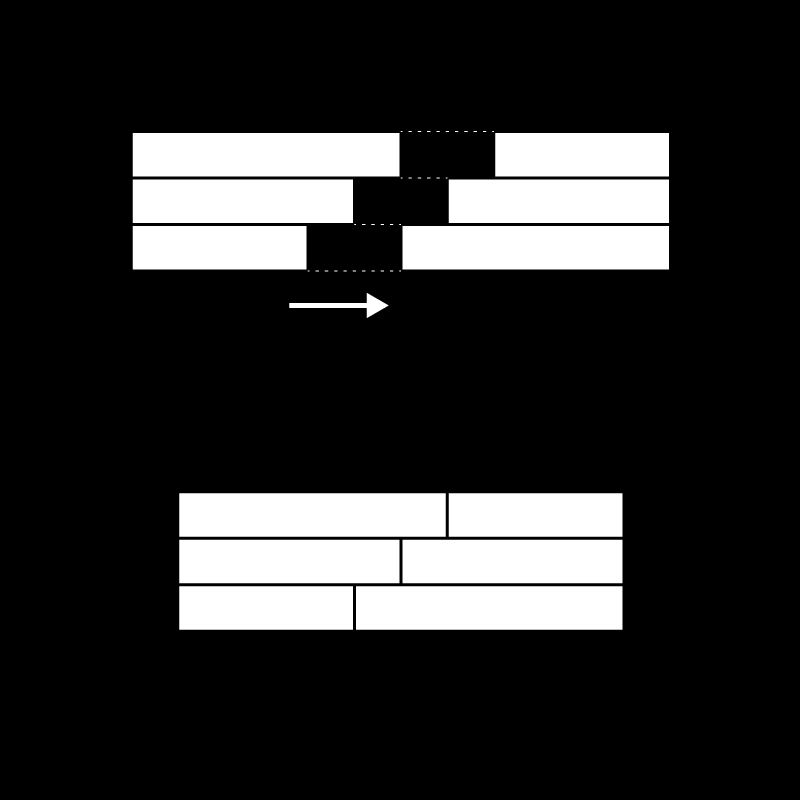
02. Expansion Joint
These sections can also be used to expand the size of stacked sheet material
03. Expansion Joint
Similar to the tongue and groove wooden joint or the male female joinery
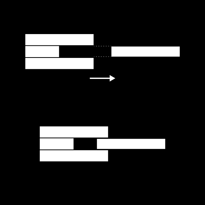
04. Channel Gap
The above section formed by stacking 3 staggered surfaces, act as a channel guide for a single sheet to pass through
Reference Study
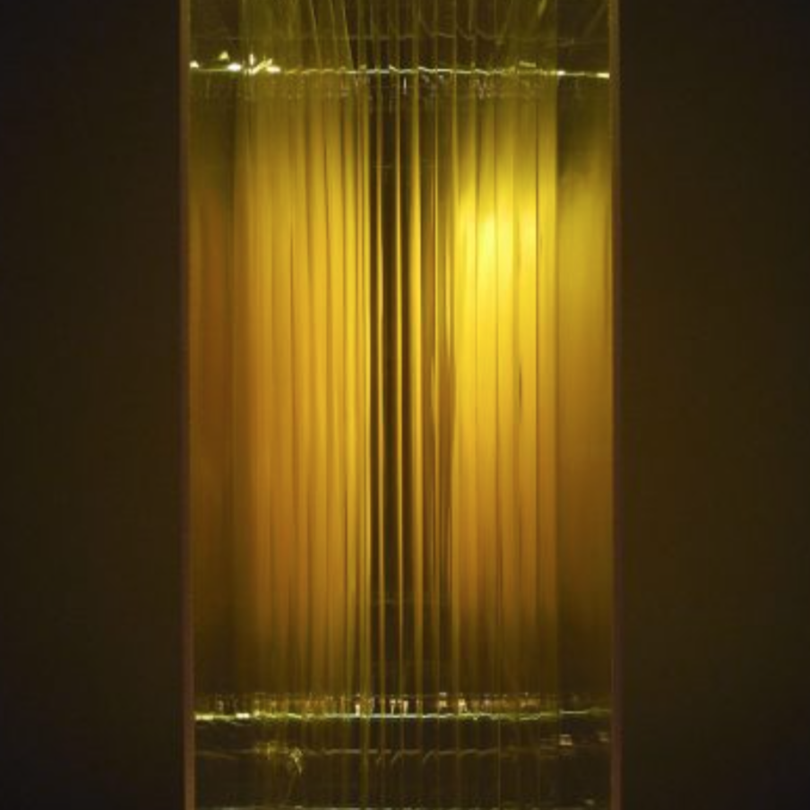
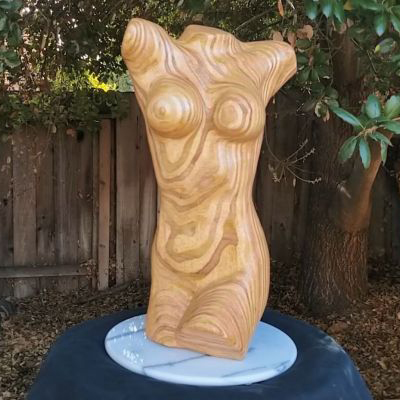 Dennis van hoof
Experiments with stacking plywood in multiple axis and CNCing sculpted forms to reveal the organic grains of the material edges.
(F) Folding
Introduction
Description:
A single surface can be folded into multiple surfaces that create a 3D object. Splitting up a 3D object into multiple foldable parts allows for portabilty and allows ease of transportaion and storage. Folding a surface in a particular format also increases its structural integrity.
The roots of the folding geometry lie in folding simple planar material like paper through origami. Now they have now found its applications in more complex dployable mechanisms.
We have explored development of surfaces as well as a few crease methods and patterns to undertand the potential of folding surfaces.
Materials:
• Paper (various GSM)
• Steel, aluminium Sheets
• Corrugated Card
• File Card
Helpful Software:
• Pepakura
• Slicer for fusion 360 (Slicing Software)
• Deep Nest (Nesting Software)
• Autodesk Fusion 360 or Grasshopper for Rhino (Parametric Modelling)
• Blender or Cinema4D (Digital Sculpting)
• Sketch Up or Rhino (Conceptual Modelling)
• Autodesk Autocad
Understanding
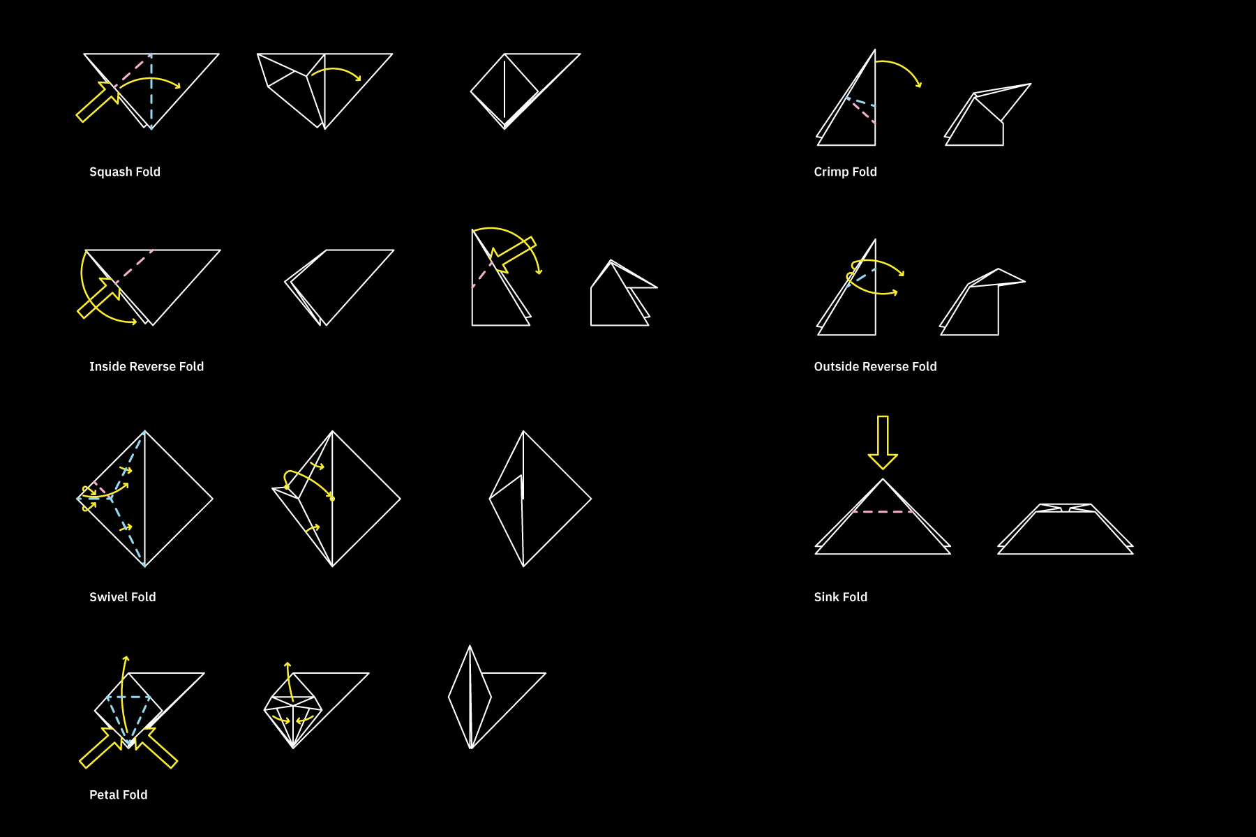
Symbols Nomenclature
Below are universal symbols used to represnt folding instructions.
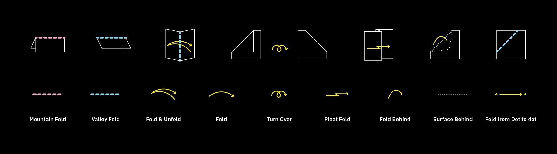
Inspired by Origami, here are different kinds of folds possible with thin surfaces.
Creases
A crease is a line on a planar surface produced by folding along that line.
In thinner materials like paper, these creases are easy to create.
Whereas in slightly thicker materials with higher density, perforations might be required along the creases line. These perforations reduce the torsional stress along the crease line, making it easy to fold along the crease axis. Perforated crease folds are commonly used in thicker materials like steel, aluminium sheets.
Crease Patterns
Different kinds of folds can be made along different composition of crease patterns. Paul Jackson’s book Folding Techniques, uses paper as a base material and explains the potential of folding techniques very thoroughly. Like Ikea instructions, origami instructions diagrams in the book are a language by themselves. Learning from the book, we have experimented with different crease patterns to represent folding can morph a 2D flat surface into a 3D form.
Pattern 001
Pattern 002
Pattern 003
Pattern 001 Folded
Pattern 002 Folded
Pattern 003 Folded
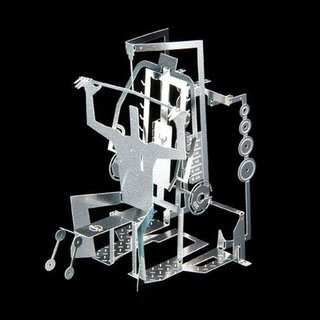
Deployable Structures
Folding also allows a surface to be compressed into a compact version and expand itself into its complete form. These mechanisms have a lot of applications when it comes to transportation, storage and engineering. Brigham Young Universities CMR (Compliment Mechanisms Research Group) involves students and faculty who are involved in the fields of Compliant Mechanisms , Developable Mechanisms and Origami-Inspired Mechanisms.
Deployable example 001
Deployable 002
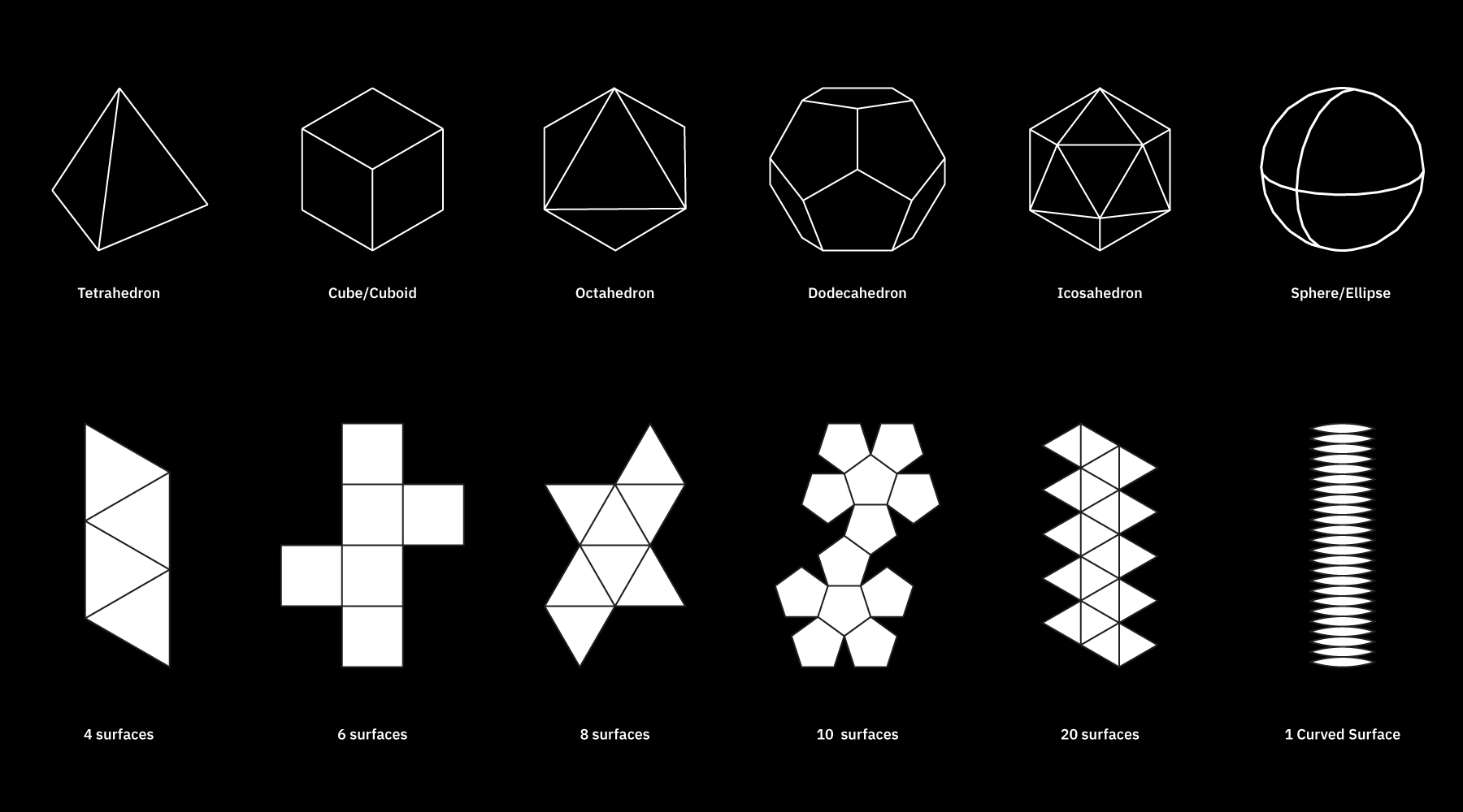
Surface Development for Basic and Complex Geometries
Many dots make a line, many lines make a surface and many surfaces make a 3D object. 3D objects with a Gaussian curvature as 0 are developable.
A developable surface is a surface that can be opened up or unfolded into parts of flat surface.
The figure below shows unfolded versions of the 3D objects in a flat format. These flat formats include the number of surfaces and their shape that make up the 3D object.
Likewise, all developable 3D object can be opened up into a series of flat surfaces, which can be folded and joined together.
3D objects and surfaces that involve curvatures in multiple axis, such as a sphere, need to be simplified in order to be developed.
Complex sculpted geometries can be converted into simpler developable surfaces too.
This is done with the help of digital tools like Pepakura or Slicer by fusion 360, which convert STL/OBJ file into developed surfaces.

Complex Organic Sculpted form
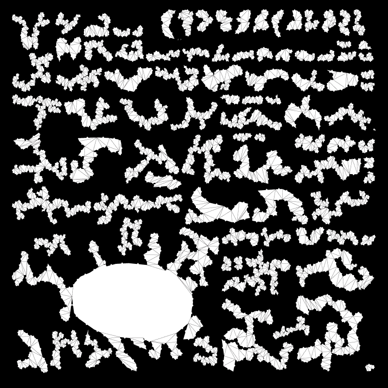
Developed surfaces that can be joined together
Simplified developed geometry
Reference Study
 Compliant Mechanisms
Is a reseach group that is involved in the field of Developable Mechanisms and Origami-Inspired Mechanisms.
 Joseph Choma
He is the author of Morphing: A Guide to Mathematical Transformations for Architects and Designers. which looks into the intersection of mathematics, folding, structure and materials.
(G) Bending
Introduction
Description:
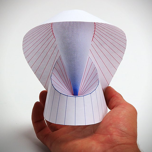
Sheet materials with extremely low bending capacity do not have the ability to fold or curve. But this can be easily changed by adding kerf cuts along the surface. A slit made perpendicular to the thickness of a material is called a kerf cut. They essentially reduce the thickness of the surface at regular intervals, since thinner sections are easier to bend.
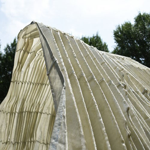
The orientation and form of the kerf cuts determine the ability of the sheet material to bend organically into any desired three dimensional form.
In a small book, DIGITAL Gehry Material Resistance Digital Construction (Bruce Lindsey, Bitkhäuser 2001) writes that if flat piece cost one dollar, single curvature piece cost two dollars, double curvature piece cost ten dollars. This is true for all materials.
Materials:
• Ply wood Sheet
• Acrylic Sheet
• MDF Sheet
• Balsa Wood Sheet
Helpful Software:
• Adobe Photoshop+Illustrator
• Autodesk Fusion 360 or Grasshopper for Rhino (Parametric Software)
• AutoCAD (CAD)
Understanding
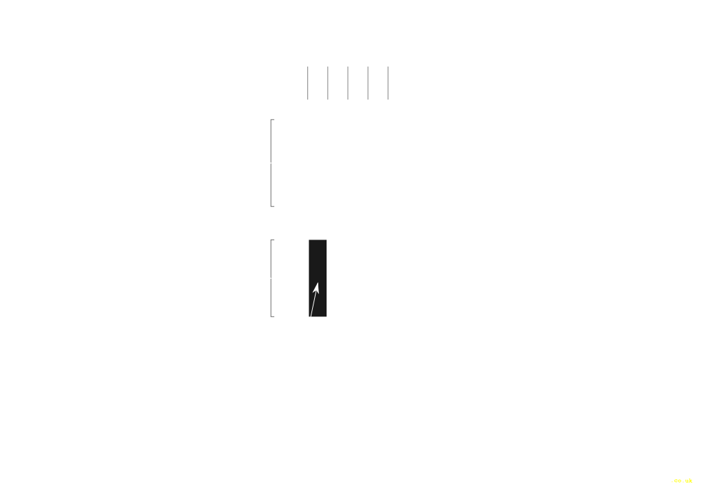
Simple Straight Kerf Cuts
A two dimensional surface can be bent simply by the help of living hinges.A living hinge is made of the same material as the two pieces it connects. It is either a cut or a thinned portion, that allows the surface to bend. Due to the reduced thickness, it becomes easier for the material to defrom at that point.
The cut (also known as kerfs) can be along a single line or multiple lines, based on the material and the radius of the bend. The parameters would vary with respect to the physical properties of the material.
With the help of kerfs, sheet materials can be bent by a particular radius along a single axis.
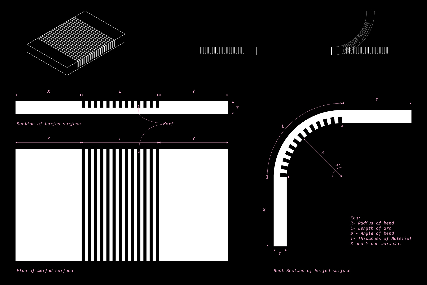
Kerfs are usually made perpendicular to the thickness of the sheet material.
The number and distance of the kerf lines are dependant upon the following parameters:
• Angle of Bend (ø)
• Radius of the curve (R)
• Thickness/Width of the kerf, based on the tool that is being used (T)
• However the optimum depth (D) of the kerf cut cannot be pre-determined. It depends on the physical properties of the sheet material in hand. So it is advised to test the kerf depth once on scrap material before.
The number and distance of the kerf lines is determined in the following way:
001 //
The Length of the arc (L) essentially helps us determine the length of the sheet material that would have kerf marks.
Length of the Arc (L)= R x ø
002 //
The number of kerf marks can be determined by the following formula’
Number of kerf marks (n)= 0.133 x ø
(rounded of the closest integer)
003 //
The Kerf distance (K) is the distance between the kerf lines within the protion of the sheet material covering the arc length.
Kerf Distance (K)= L / n
For example:
180deg(ø) bend- 24 lines of kerf will be divided equally along the lenth of the arc
90deg(ø) bend- 12 lines of kerf will be divided equally along the lenth of the arc
This method helps us understand the logic behind bending sheet materials and can be easily applied while making kerfs manually or with the help of CNC.
You can find a Online Kerf Spacing calculator: here
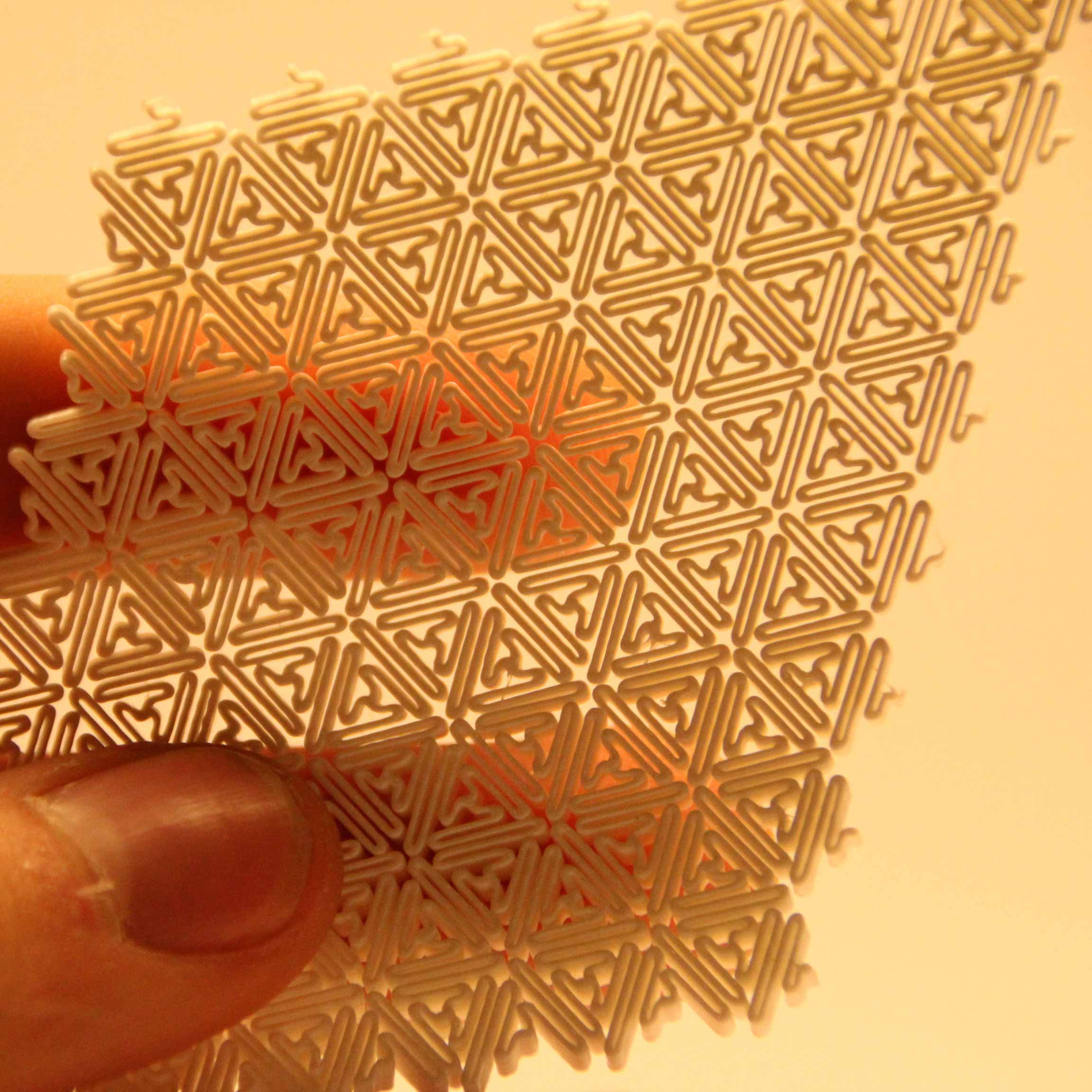
Lattice hinges
In order to increase the flexibilty of rigid materials, the straight kerf lines have been evolved into lattice hinges.
They are fomred when overlapping alternating cuts divide the surface of a material into smaller linked surfaces, as shown in the diagram below by Deferred Procrastination. These surface links make it easier for the each column to twist along its own length.
Bending in lattice hinges is caused by columns of torsional links which are easily twisted. They are interconnected on fixed points, by increasing the distance between these fixed points and decreasing width of the torsional link we can increase flexibility to a surface.
 Images from defproc
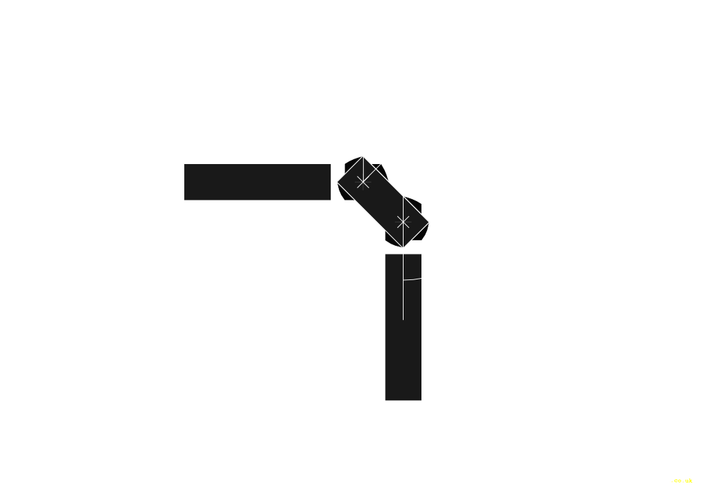
The math behind the torsional force acting on the hinge is thoroughly explained by the engineers at Defproc. You can visit the link here: (Link 1) (Link 2)
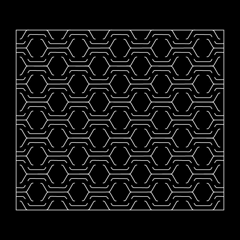
Patterns
The idea of lattice hinges has been explored further in form of 2D experimental patterns by the folks at fequalsf, obrary and kofactor lab.
We have arranged them in a hierarchy of evolution to understand and analyse the attributes of their forms.
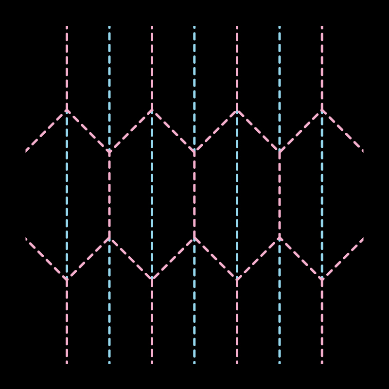
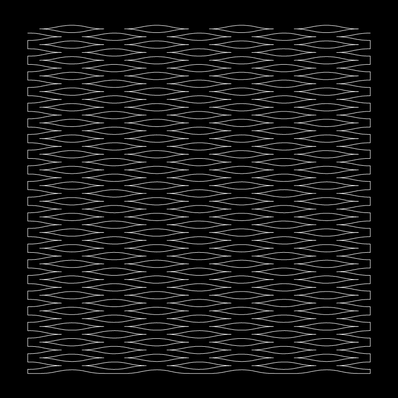
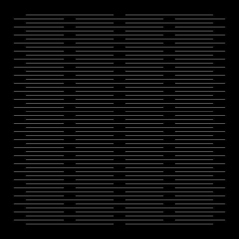 001
001Straight Lattice Here the overlapping kerf lines divide the surface into smaller torsional links, allowing them to deform in parts
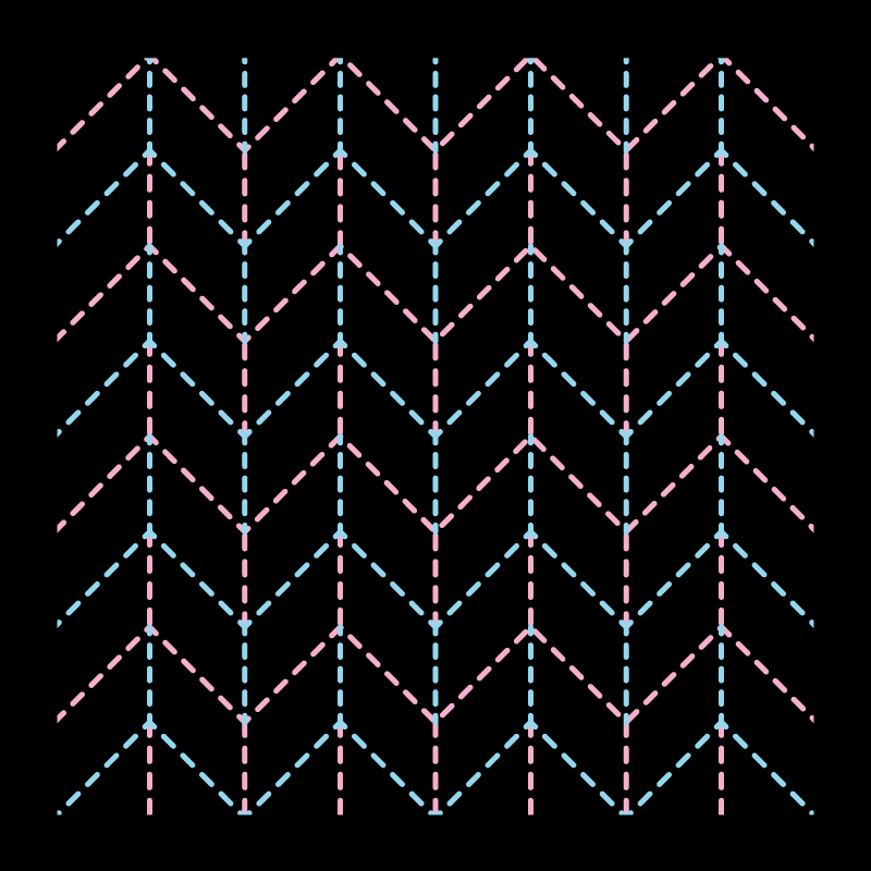
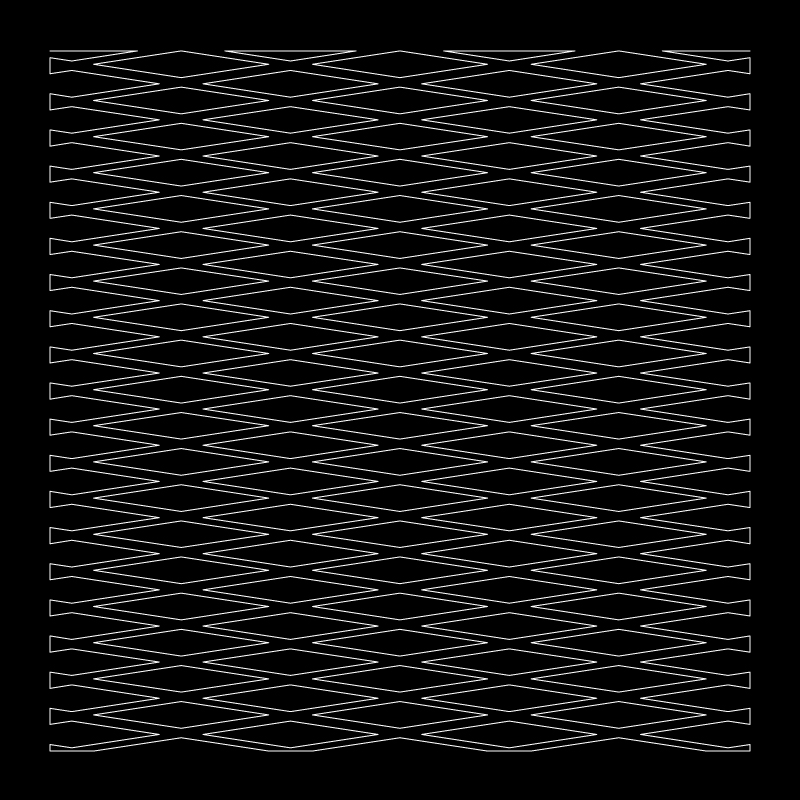 002
002Rhombus Voids • The kerf line is replaced by a void in the form of a rhoumbus. • This decreases the size of the link and increase the clearance for the link to twist. • The thin links become a cross shape with rhombus voids. • If stretched vertically the pattern become an orthogonal grid at 45º. • The shorter diagonal of the rhombus keeps the link clearance just about enough for the long link to twist.
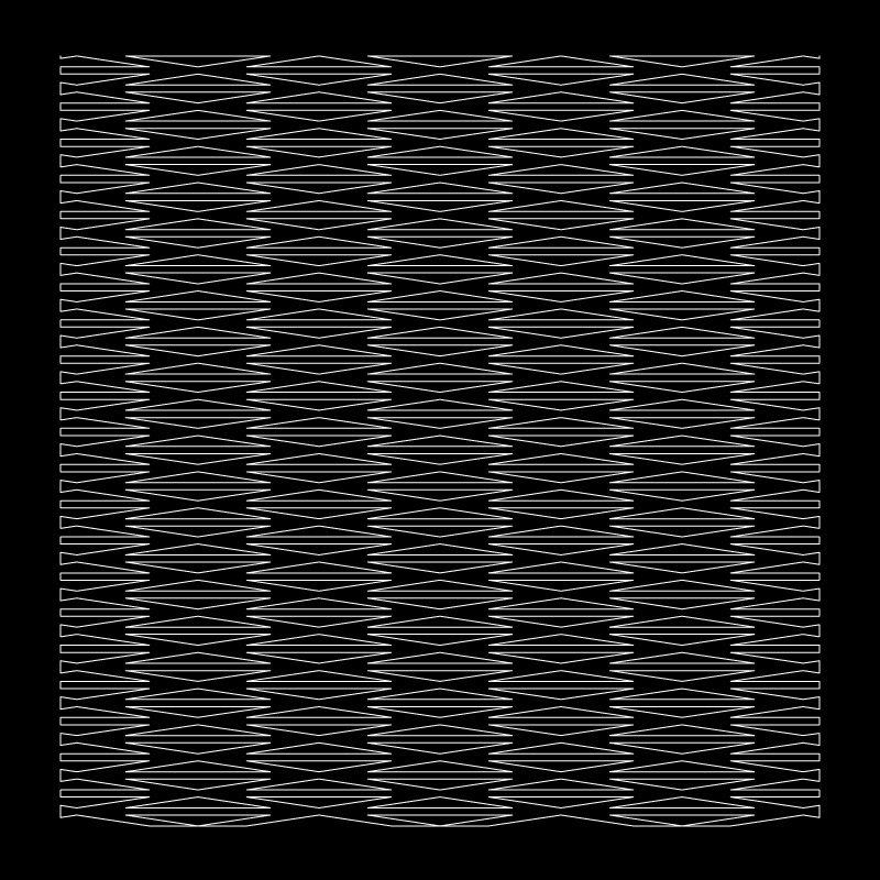 003
003
Isoceles Triangluar Voids • The longer diagonal of the rhombus are attached to form an extra link. • This in turn forms 2 back to back isoceles triangualar voids. • The extra link assists retaining the surface’s strength. • The lengths of the links variate
 004
004Eliptical Curves
• The edges of the rhombus are filletted
• Curved edges variate the widths of the lnks formed.
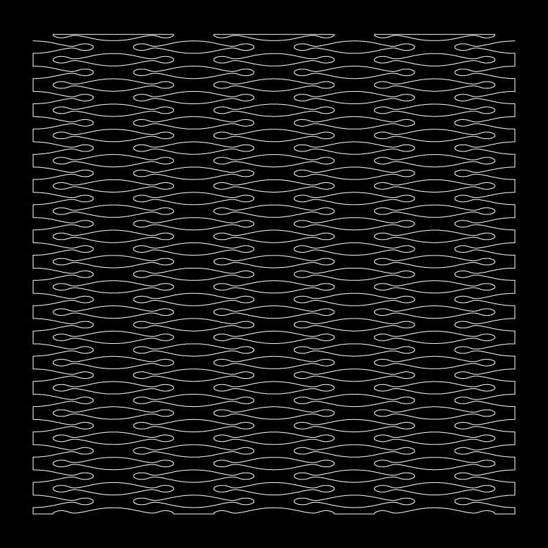 005
005 Three Elliptical Voids • The repititiv rhythm of curved voids forms undulating links of variating widths and lengths. • The organic form of the links might assist in twisting along a defined axis.
 006
006 Waves • The overlap between the kerf cuts is extremely short.
• The displacement of the the straight makes the link widths taper on either sides.
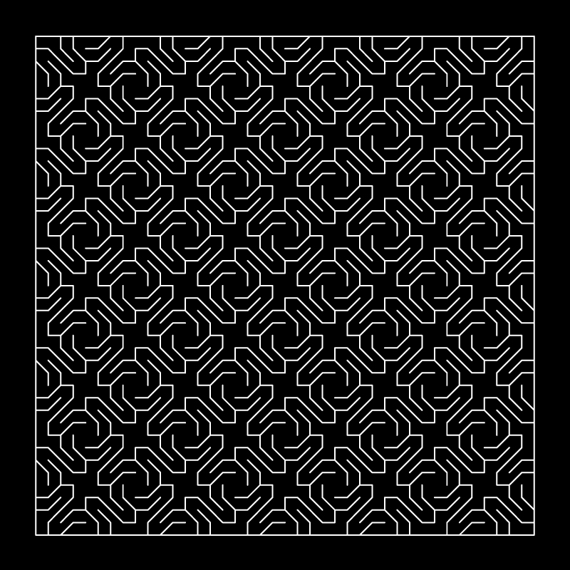
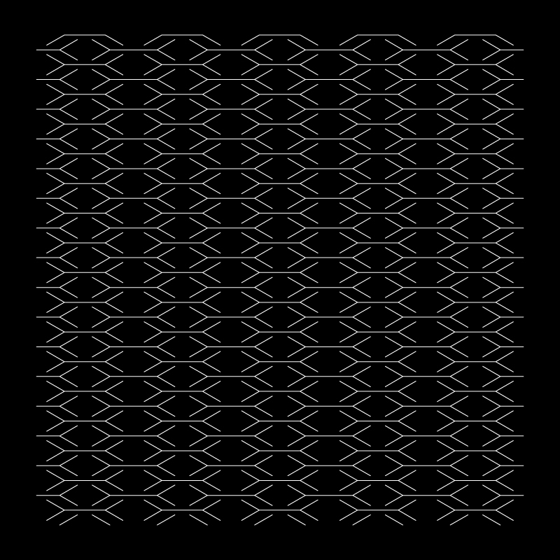 007
007 Cross Lattice
• Branching kerf cuts, forms links in 4 angles in opposite directions. • The more braches, porbably the more directions/ angles to bend in . • Concentric links formed, with a the surfaces twisting on the peripheriy of the middle piece.
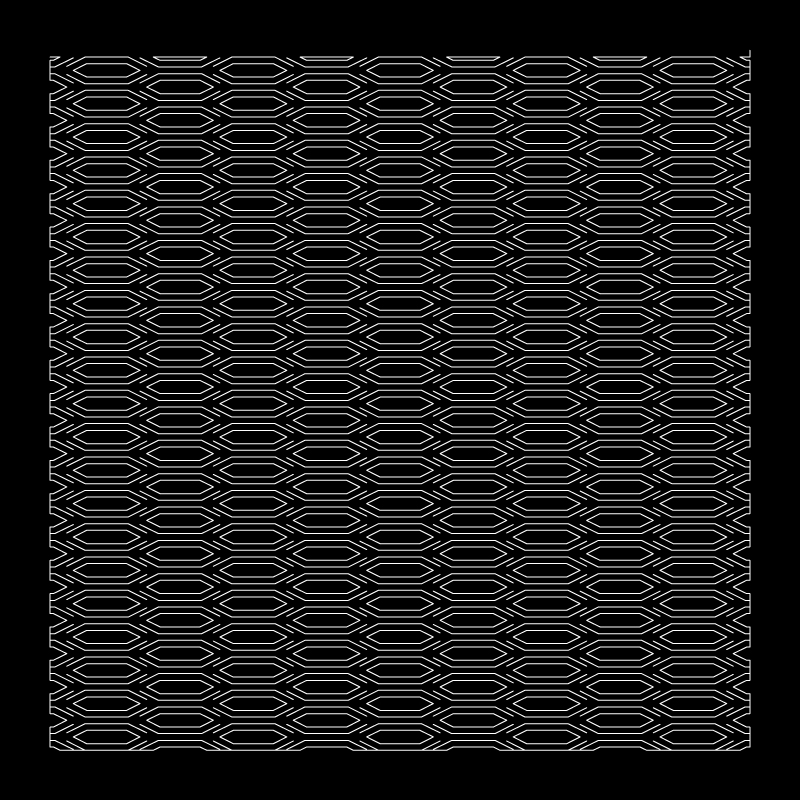 008
008 Hexagonal Voids
• Hexagonal voids with kerf cuts on the perpheriry.
• This creates different sizes of links in 6 different angles, mirrored in to opposite directin
009 Concentric Triangle The straight overlapping alternating kerf cut lines, translated into a concentric triangular format
 010 Spiral
Links formed in a perpendicular direction spiral in opposite direction. This is explained further below in Multiaxial Bending.
010 Spiral
Links formed in a perpendicular direction spiral in opposite direction. This is explained further below in Multiaxial Bending.Based on our observations the flexibility of a surface can be increased by
• Increasing the thickness of the kerf, essentially converting a cut to a void
• Preventing sharp edged corners, hence filleting the corners and edges.
• Increasing the length and width of the link
• Branching kerf cuts in multiple directions, make the torsional links twist in different directions.
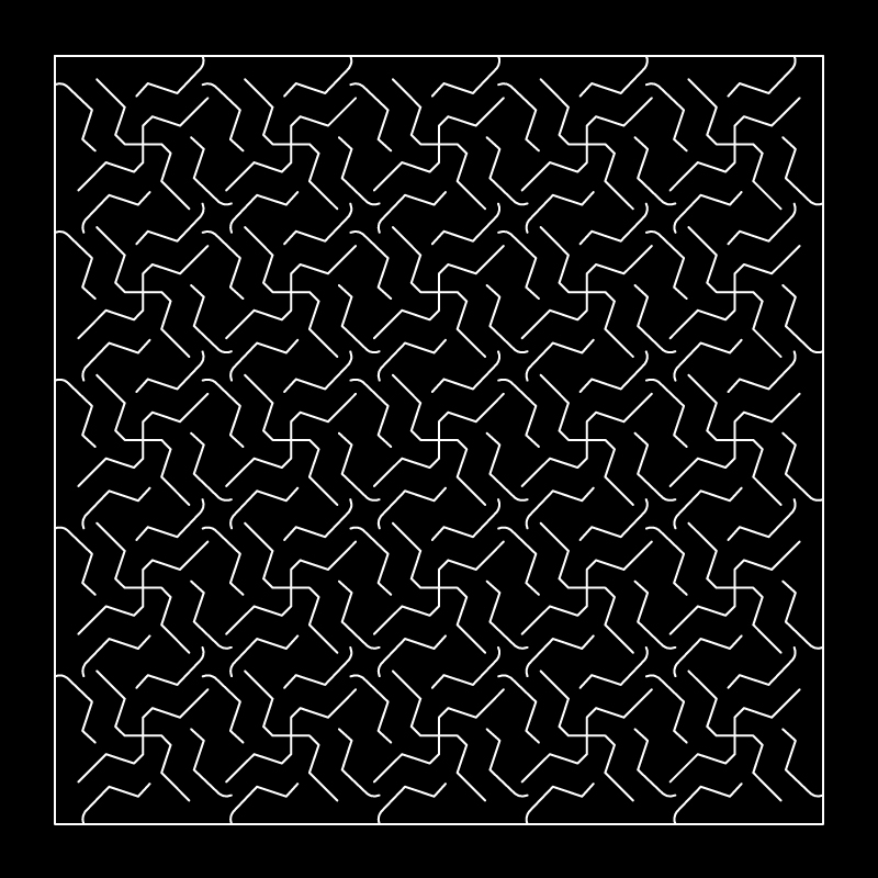
Below are a few experimental pattern developments using the combination of voids and kerfs and concentric grid systems.

You can email us for the open files of the above patterns, to experiment yourself.
You will need a CNC mill or laser machines cut these precise patterns on sheet materials like plywood and acrylic.
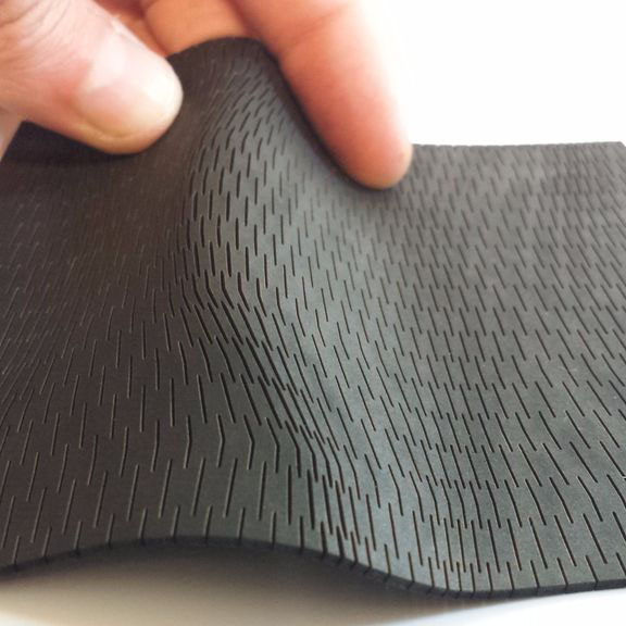
Multiaxial Bending
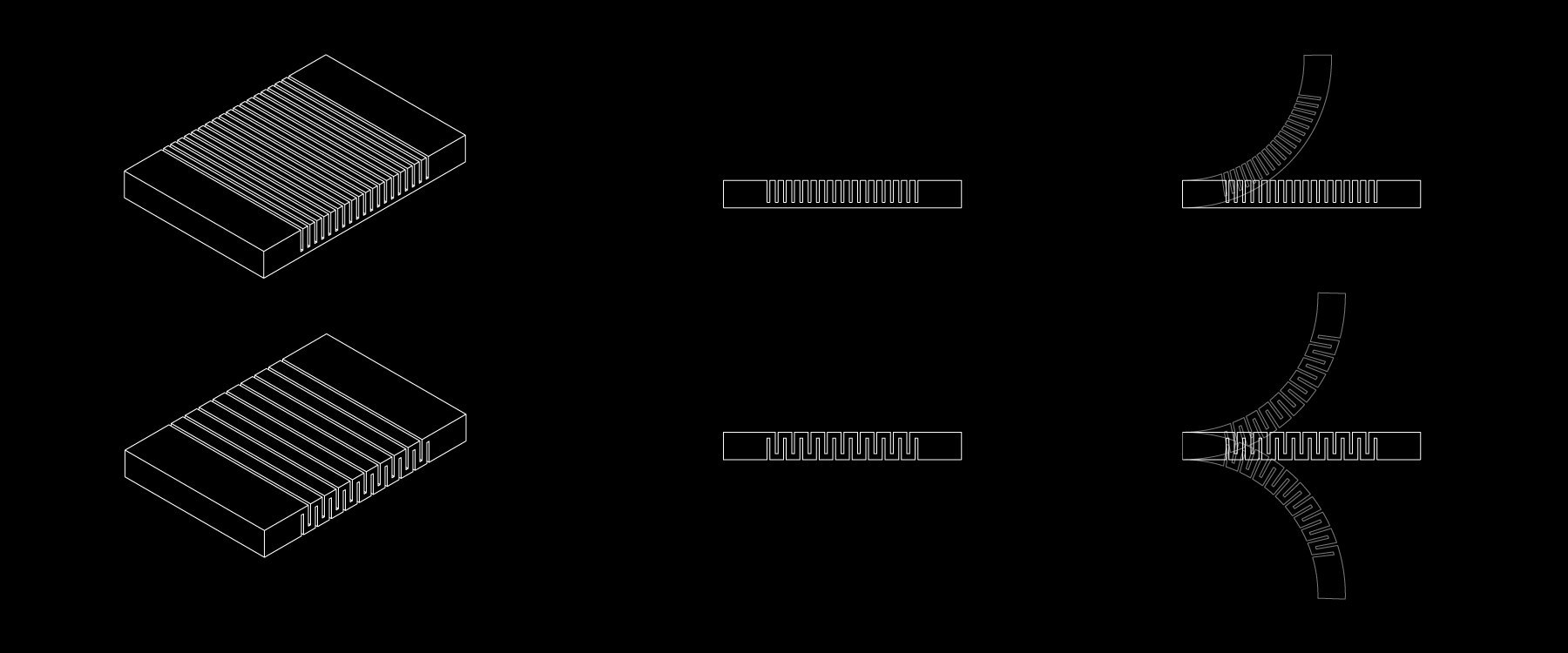
Adding alternate simple kerfs cuts on opposite sides of a thick surface enables it to bend in two directions, as shown in the above diagram.
For a surface to bend in muliple axes they can be divided into developable and non-developable surfaces.
A developable surface is a surface that can be opened up or unfolded into a flat surface. Refer to Surface development in the Folding Section.
A non- developable on the other hand cannot be opened or unfolded into a flat surface. They are made up of curves that bend in multiple axis, hence having a Positive or Negative value for their Gaussian curvature.
Curved developable surface
Surfaces can be bent in multiple directions by using lattice hinge patterns with rigid materials. To create a developable curve, a surface can be bent either by kerfs in the form of parallel lattice hinges or spiral pattern.
Lattice pattern for developable surface:
A Grasshopper experiment
We have used a method developed by fequalsf (Download grasshopper script) to understand how a lattice pattern can be applied to a curved surface. The approach is a crude approximation.
Nomenclature:
• U Count is the number of divisions in the U direction (parallel to the cuts)
• V Count is the number of divisions in the V direction (perpendicular to the cuts)
For the grasshopper script to work we need 3 inputs:
(1) 3d curved surface
(2) An Unrolled surface you can do this by unroll command in rhino ( Surface>Unroll Developable Srf ).
(3) 2d kerf pattern unit
Hereby knowing the change in curvature across the surface. Areas with very little change can have wider and less flexible hinges, while areas with a lot of change will need thinner and more flexible hinges.
The settings at the beginning of the definition will change your pattern for laser cutting. Typically it will be smaller U count and larger V count so that your lattice pattern is longer and more flexible.
The Domain start and Domain end sliders are the factors determining the curvature of the surface setting the Domain end value to somewhere between 0.4 and 0.6 tends to work the best.
For detailed understanding refer this (Link)
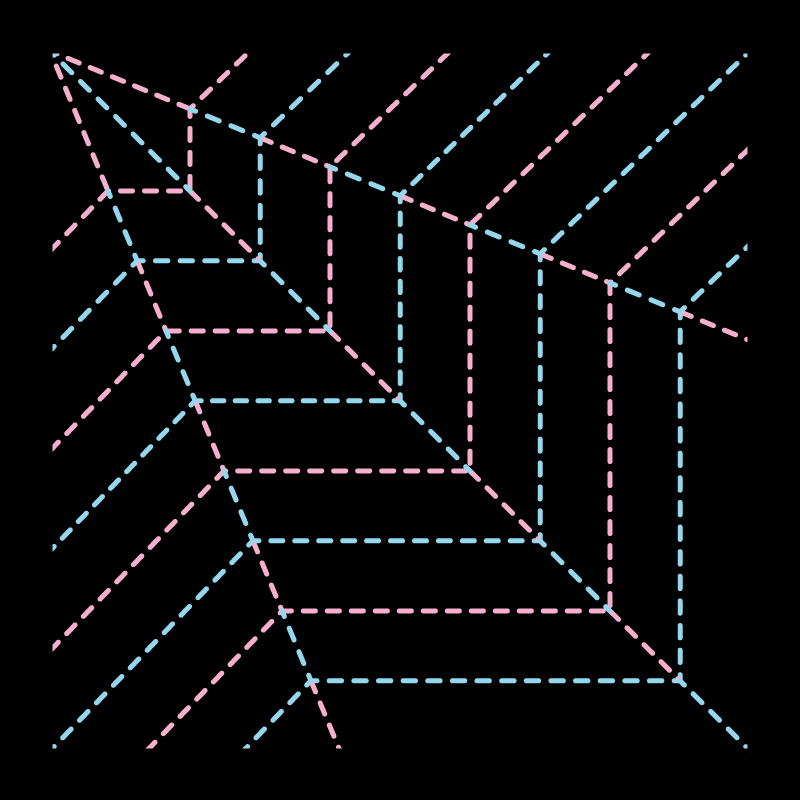
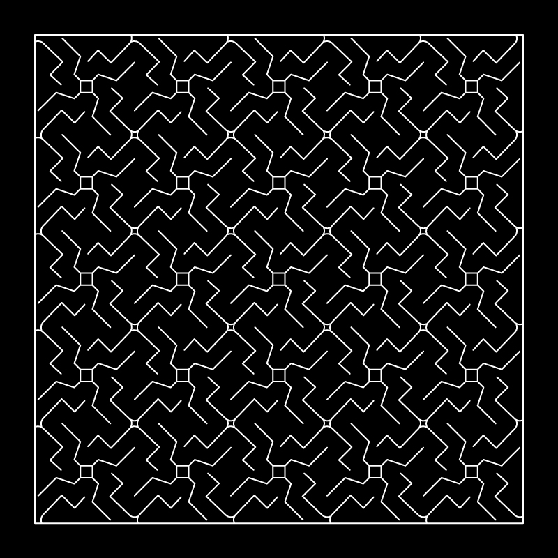
Spiraling pattern creation
The logic behind lattice hinges is translated by kofactor lab, by converting the linear parallel forms of the lattice hinges into a rectangular spiral. (pattern 10 analysed above)
This allows the segments to twist in two opposite directions simultaneously, making the distance between the fixed points longer. This all amounts to morphing a rigid surface into a flexible surface.
Below are a few experimental pattern developments using the same understanding.
Non-developable surfaces also can be formed by expanding the lattice hinge pattern, but this is possible with flexible materials only. Since flexible materials have the ability to stretch into a doubly curved surface. A flexible surface is hence allowed to stretch and open up, leaving the vertices of the lattice hinges connected. The gaussian curvature of the surface is directly proportional to opening/voids in the pattern.